With 20+ years of experience and technical support for our customers, we created this ultrasound image optimization guide to provide you with an easy to read manual to understand and to get the best images from your ultrasound machine. Oftentimes manufacturer presets are not “optimal” for your practices needs, so learning how to adjust your ultrasound machine’s specifications will help you achieve better clinical results with the best images and become more efficient.
Navigation Menu:
Introduction
A. What is a “good” ultrasound image?
- Brightness/Contrast Settings
- Presets
B. Basic Image Optimization Techniques
- Gain Control
- Time Gain Compensation controls
- Focal Zones
- Frequency Selection
- Auto Optimization
C. Tissue Harmonics, Speckle Reduction Imaging, Compound Imaging
- Tissue Harmonics Imaging
- Compound Imaging
- Speckle Reduction Imaging
D. Beyond the Basics: Advanced Image Optimization
- Dynamic Range (Compression)
- Ultrasound Gray Maps
- Line Density
- Frame Average/Persistence
- Rejection
- Edge Enhance
Taking Control
It can be an intimidating experience when you first look at an ultrasound and physicians can quickly realize that using these machines isn’t as easy as it seems. In my experience, it’s been a tough learning curve, which is why I created this guide to help you avoid any complications. Physicians regularly express their confusions to me; they open the box, see a bunch of foreign knobs and buttons, and frustration sets in. Coupled with a poorly designed user manual, it only adds to their confusion, leaving them to stare at a screen and feel lost once they turn it on.
From my experience over the past 20 years, I’ve found a simple solution; learning where to begin and understand what knobs and buttons truly matter.
This guide is for physicians and clinicians who often do not receive formal training for their ultrasound machinery. By simply testing a few controls, you can quickly gain a basic understanding of ultrasounds and become a master at image optimization.
In this guide, I’ll begin by clarifying the key controls and functions for optimizing your ultrasound images. Deeper in this guide, we’ll help you fine-tune and fully understand your ultrasound through understanding the more advanced technologies.

Don’t let your ultrasound overwhelm you.
Grab your user manual for reference
Every user manual has a section in the front which outlines the location of different controls. Find that page and leave it open. If you can't find a hard copy of the manual, press the F1 key on your keyboard, this will typically open the electronic manual. As a reference, take a picture of this page with your phone or tablet to refer back later.
What is a "good" ultrasound image?
Good image quality is relative to the capabilities of the machine and is fairly subjective and. Two people looking at the same image will frequently have a different perspective on their interpretation on what is “good.” Experienced users are used to the image quality they see and often want these imaging capabilities to be similar to their old machines. New ultrasound users want images that fit their brain’s perspective of what they perceive the anatomy is supposed to look like. Yours and others' opinions may change over the course of you mastering the ultrasound, but in the end it's up to you to decide.
Note: I’ll refer to musculoskeletal imaging (which includes needle guidance) because it’s the most common type of user I speak with and these steps apply to all modalities.
Before you start, adjust the brightness and/or contrast on your monitor
One of the most important steps, particularly with CRT (non flat-panel LCD) monitors is balancing the brightness and/or contrast to get the clearest images. On machines with CRT monitors, user manuals will list these recommended steps in enabling these imaging specifications. Most manufacturers recommend starting with 90-100% contrast, then adjusting the brightness if necessary.
The greyscale bar (shown below) shows the ultrasound’s current imaging greyscale from white to black. Begin by setting the lighting in the room to match the lighting you’ll use when scanning to ensure best visibility. Next, turn your brightness to the highest point, then concentrate the grayscale bar to the very bottom which will be at its darkest point. Slowly turn the brightness down until the darkest level is black and no longer visible, leaving the top to be white, but not over-saturated. If you have a contrast adjustment (which many portable machines do not), you can set the specifications to meet your preferences. Note that your brightness setting will be impacted after adjusting the contrast.

Grayscale Bar
The brightness setting is the only consistent adjustment that remains with every new exam. Unless you go through specific steps to save a custom preset, the remaining settings following will not be saved to the ultrasound. So feel free to experiment because you can start over by reselecting the preset.
Tip: Be ambidextrous or seek help
In these following steps, you’ll be interacting with a live image. If you don’t have an assistant, put some gel on a probe, and with your right hand and place the probe on your left wrist or arm. As you make adjustments with your left hand (or the opposite for left-handed individuals), you’ll see what happens on a live image. Don’t worry about making the image perfect, you're just practicing.
Tip: Try different ultrasound presets, for some, MSK may not be the best starting point
Many factory presets are poorly set up for the user interface. On older machines, it is best to try out different settings because MSK and needle guidance/nerve settings are not commonly studied.
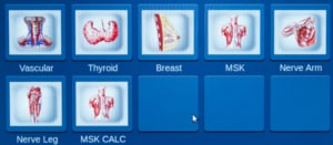
For needle guidance and MSK, you can generally skip abdominal, cardiac, OB/GYN, and urology settings when using a linear probe. Alternatively, look for any preset associated with superficial imaging such as small parts, default, venous, peripheral vascular, breast, nerve, thyroid, and different user settings (user 1, user 2, user 3, etc). Repeat these steps until you have a solid grasp of these reference points. Take a note of your favorites. For the upcoming steps, choose one and stick to it, you can go back over the other controls once you’ve gained a firm understanding.
Note: Calculations are affected by the presets you choose. MSK is generally not an issue, but in other modalities, M&A (measurement and analysis) packages are associated with the preset. You can set the M&A package to a custom preset, but because it’s unique to each machine, it’s beyond the scope of this series.
Basic Optimization Techniques
In the beginning, everyone must understand these basic controls. You’ll frequently be using them no matter how advanced you get. In this segment, you’ll learn what controls that you will most often use during all of your exams.
Don’t fear the gain control
The gain knob adjusts the overall brightness of the ultrasound image and will most likely be your go-to for imaging control. It will soon become second nature adjusting it, you’ll be surprised at how a simple twist can have a great impact on your image quality.

Gain Adjustment
TGC: Time Gain Compensation controls
Each machine has 5-10 slide controls grouped together (TGC or Time Gain Compensation controls), with the exception of several tablets and the SonoSite. These controls adjust gain in particular areas of an image (far-field, mid-, and near-). The easiest way to see what a control does is to experiment by looking at a live image and seeing what happens when you slide any one of the controls all the way to the right, then all the way to the left. You’ll notice that a certain section of the image turns very bright at first and then very dark as you slide to the left.
When starting up your new ultrasound techs typically adjust these to left-of-center for nearfield (top) imaging, and gradually move to right-of-center as quality decreases deeper in the image. The goal to getting a crisper image is to have a lower gain in the nearfield while having a higher gain deeper in the image, where image quality is fainter.

TGC Sidepots
SonoSite users: The general equivalent of TGC are two separate gain knobs that control farfield and nearfield gain.
Ultrasound Focus position, focal zones
When determining the depth at which you’d like the highest resolution, you will need to use the focal position. These image optimization features are important, but are often-overlooked. When you shift the focal position up and down, you’ll see a dot or triangle move up or down on the right or left side of the image. This will improve the image resolution in the selected focal position area.
Focal zones allow the user to have multiple focus points. Increasing the number of focal zones will make your frame rate decrease and images refresh slower.
Frequency Selection
Adjusting the frequency allows you to increase penetration at the expense of resolution, or visa versa. Most transducers are broadband, meaning that adjusting the frequency will usually display a range of frequencies, not just a single frequency. Some machines show the actual frequency range (represented by MHz), while others will not show frequency and alternatively offer the choice of either “Pen”, “Gen”, or “Res” (“HARM” or “Harmonics” will be addressed later in this guide).

On these transducer’s, “Pen” describes the lowest range of frequencies meant for deeper tissue and difficult-to-image patients. “Gen” describes mid-range frequencies that are typically the default setting. “Res” describes the highest frequency band for superficial imaging. Try a different setting for each image you take, based on what anatomy you’re viewing, you’ll need the highest possible frequency setting.
Some machines show a specific frequency or range of frequencies. In this case, use lower frequencies when you need penetration when imaging. Lower frequencies provide the best penetration, but at the expense of image resolution. Higher frequencies provide the best resolution when looking at superficial imaging, although you will lose penetration.

Frequency Adjustment
Auto Optimization
Many ultrasounds have a feature that automatically optimizes the overall contrast and gain of the image, typically called a variation of one of the following names: Auto Optimize, Auto Tuning, or Tissue Equalization. This feature examines the tissue in the image and seeks to provide the most optimized image. Most users neglect this button, but it’s a great starting point once your presets, depth, frequency and focus are dialed-in.

Words to the wise:
- If you run into a problem or overoptimize your image, reset to your originally selected preset. Simply return to the preset or exam screen and select your originally chosen preset. This resets all of your changes, which allows you to start anew.
- Once you’ve made adjustments to your liking, every recent machine allows you to save a custom imaging preset. However, the steps in doing so all vary and can’t be covered here, so refer to your user manual and make sure to write down what settings you prefer.
Tissue Harmonics, Speckle Reduction, and Compound Imaging
Over the past 20 years, three new mainstream technologies have been introduced that have dramatically impacted ultrasound image quality. These imaging features would be the Tissue Harmonics Imaging, Compound Imaging, and Speckle Reduction Imaging. It is rare for a machine not to have these three core technologies today.
Learning how to use them properly is an important step for getting the best image quality from your ultrasound. In these following steps, I’ll review their basic concepts, how to use them, and what the technologies do.
Note: Most manufacturers use some form of the name “harmonics,” however, Speckle Reduction and Compound Imaging are given different names by every manufacturer. Consult your user manual to find these on your machine.
Tissue Harmonics Imaging
What: Harmonics imaging assists the ultrasound in reducing the artifact in the image and identifying body tissue. This does it by sending and receiving signals at two different ultrasound frequencies. For example, with harmonics equipped, a probe will emit a frequency of 2MHz, but only “listens” for a 4MHz frequency response. Body tissue reflects sound at twice the frequency than what was initially sent, which results in a crisper image that better displays the body tissues image quality with less artifact. You can see how image artifact is reduced to give you a more defined image of the body tissue through the below image demonstrating a signal sent at 7 MHz and received at 14MHz.
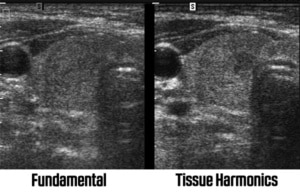
Tissue Harmonics allows the ultrasound to identify tissue better and reduce artifact or “noise” in the image. Adjusting levels of harmonics helps optimize an ultrasound image.
Why: Harmonics is useful in most situations, especially on difficult-to-image patients when the image has a lot of “noise”. However, it doesn’t necessarily help for very superficial or deep tissue (varies depending on transducer used). You’ll find many presets on your machine that will have harmonics enabled and disabled so be sure to try them all by turning the ultrasound on and off in different situations to see what helps.
How: A device with harmonics will have a “Harm,” “HI,” “THI,” or similar control/button on the ultrasound. When enabled, the Frequency control typically is used to adjust the device. The frequency display will change from displaying frequency range (in MHz) to High, Mid, and Low or Gen, Res, and Pen,. “High” and “Res” are for superficial tissue whereas “Low” and “Pen” are for deep tissue imaging.
Drawbacks: In regard to deep penetration, the image can disappear completely when viewing deep tissue. To avoid this issue, you’ll need to turn this imaging feature off for your most difficult-to-image patients (in particular obstetrics).
Speckle Reduction Imaging
What: Speckle Reduction Imaging (SRI, XRES, uScan, etc) uses an algorithm to identify weak and strong ultrasound signals. By assessing the image on a pixel-by-pixel scale, it attempts to eliminate “speckle” and identify tissue, providing the user with an overall smoother, cleaner image. Weak signals that seem to be amiss are removed, while strong signals are brightened and enhanced. The following image depicts an image with Speckle Reduction enabled.
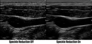
Speckle Reduction uses an algorithm to reduce “speckle” in an ultrasound image while improving images of tissue.
Why: Through this technology the user can identify tissue better, make easier measurements, and view a much cleaner image. Most ultrasounds equipped with Speckle Reduction have it “on” for nearly all of their presets and it will rarely be “off.”
How: Most ultrasounds offer varying levels of Speckle Reduction. The lowest level will only lightly enhance tissue and reduce small amounts of artifact, while the strongest levels can make the image look over-processed. The standard way is to have it set near mid-level. This technology is meant to be used post-processing, meaning you can adjust its level once your image is frozen. For easy access imaging, take your image, freeze it, then adjust its Speckle Reduction levels to see how the image is affected.
Drawbacks: When set too high, the image can look like crumpled paper because the image quality is solely dependent on the internal computer, resulting in slower frame rates.
Here are the different manufacturer names used for these technologies:
| Technology | Manufacturer Names |
|---|---|
| Speckle Reduction | SRI, SRI HD, XRes, iClear, Adaptive Speckle Reduction, MView, SCI, SonoHD, ApliPure+, TeraVision, SRF |
| Compound Imaging | CrossXBeam, CRI, SonoCT, iBeam, OmniBeam, XView, SonoMB, ApliPure, Spatial Compounding |
Compound Imaging
What: Compound Imaging combines three or more images from different steering angles into one single image. Without compound imaging, transducers are used to send ultrasound signals in a single “line of sight”, meaning it listens for the echo by sending a sound signal perpendicular to the probe head. Through compound imaging, the ultrasound can “see” tissue from multiple angles by sending signals at multiple angles, eliminating artifact in the imaging process. The following image depicts what’s really happening:
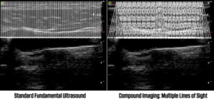
The image on the left shows the fundamental ultrasound signals perpendicular to the probe. The right shows compound imaging sending and receiving signals from different angles.
Why: Image resolution is increased with compound imaging by using multiple lines of sight to eliminate shadows, artifacts, and increase edge details.
How: Manufacturers have many different names for their compound imaging technologies, such as CrossXBeam, SonoCT, and others. You’ll need to find this technology, but in most cases it is on by default on your system.
Drawbacks: Several shortcomings of compound imaging are as follows: It’s less effective the deeper the penetration. It’s not necessarily effective in extreme superficial imaging. Its frame rate is slower with the more lines of sight you use. Sector transducers are not available. Compound Imaging is only available on convex and linear transducers. Some manufacturers simply don’t do it well and occasionally the image is better with it off.
Extra bonus: On some machines you can use 2D “Beam Steering”, which can make a big difference in needle visualization because the beam reflects perpendicular to the needle. The resulting image shows a brightened image of the needle.
Beyond the Basics: Advanced Image Optimization
The settings or “presets” that come with your ultrasound machine are designed by a team of engineers and sonographers, or possibly a single sonographer. Those technicians create settings based on their opinion of the best image. Often, the manufacturer’s factory presets are general settings copied from previous machines, or replicate a different manufacturer’s settings.
With this in mind, if you want the best image quality from your ultrasound, experiment and learn what you like. Previous sections of this guide provided you with the basic knowledge behind the technology, but next we’re diving into secondary controls that can have a dramatic impact on the display of your image.
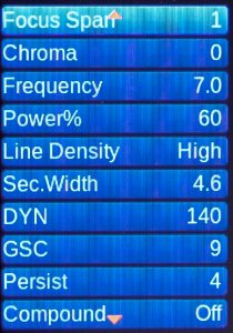
Don’t worry, adjusting these settings won’t permanently affect your machine unless you specifically go through the steps to save a preset. You can always reset to the default by reselecting the exam preset from your exam or transducer menu. Worst case, reboot the machine.
Secondary controls are available on practically every machine (some tablets and the SonoSite ultrasounds may not have these). These seemingly obscure functions determine how the ultrasound will display and interpret the image. As you’ll learn, your image can dramatically change when using these controls. Note that no single “perfect” image exists, only that in the eyes of the beholder.
Dynamic Range (Compression)
Dynamic Range (or Compression) lets you tell the ultrasound how you want the echo intensity displayed as different shades of gray. A wide/broad range displays more shades of gray and a smoother image overall. A narrow/smaller range displays less shades of gray that appear at a higher contrast with a more black-and-white image.
Some manufacturers (such as GE) call it Dynamic Range on a live image, then change the name to Compression once you freeze your image, which is often a confusing feature.
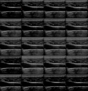
The Dynamic range's effect on the same image
Dynamic Range and Gray Maps affect one another. If you change one, you may want to adjust the other.
Ultrasound Gray Maps
Although different, changing the gray maps on your image will have a similar effect on an ultrasound image as it would be when changing the dynamic range. A gray map decides how light or dark you prefer to show each level of white, gray, or black based on the strength of the ultrasound signal, whereas Dynamic Range adjusts the number of shades of gray overall.

The curve on a grey map
Plainly put, gray maps adjust the brightness of each shade of gray, whereas dynamic range decreases or increases the number of gray shades provided.
These settings are quite different, although they may appear to have similar effects on your image. It usually helps to adjust them in combination with each other to find an image that works best for you.
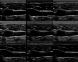
The gray map’s effect on the same image
Line Density
Line density adjusts the number of scan lines on your ultrasound image. A higher level will provide better image resolution (more scan lines), but will reduce the frame rate. This feature will get you the best possible image with an acceptable frame rate.
Frame Average/Persistence
Frame averaging (or persistence) is a similar function that combines or “averages” multiple image frames into a single image. It has a similar effect to Speckle Reduction for it produces a smoother image with reduced noise.

Reject
Reject (or rejection) filters tell the ultrasound the minimum level of echo to display. For instance, if your image has a lot of noise, increasing the Reject level will suppress the weakest signals, cleaning up the image.

Enhance/Edge Enhance
With Edge Enhancement, the machine attempts to sharpen the image by combining adjacent signals, which helps show brighter edges of structures and higher contrasts.

Creating Custom Presets
You can save your custom presets on practically all modern ultrasounds (some tablets and the SonoSite ultrasound may not have these). You can find these in the system settings, but it’s easiest to refer to your user manual for it is different on every machine (F1 key on most systems).
Using these adjustments to optimize your ultrasound image
Mastering these adjustments will allow you to set your own custom presets and help you to make adjustments in real time while imagining. With some experimenting, you’ll become an expert on how to optimize your ultrasound machine in no time.
About the Author
Brian Gill is Probo Medical’s Vice President of Marketing. He has more than 20 years of experience in the ultrasound industry. From sales to service to customer support, he has done everything from circuit board repair and on-site service to networking and PACS, to training clinicians on ultrasound equipment. Through the years, Brian has trained more than 500 clinicians on over 100 different ultrasound machines. Currently, Brian is known as the industry expert in evaluating ultrasounds and training users on all makes and models of ultrasound equipment, this includes consulting with manufacturers with equipment evaluations during all stages of product development.

